
ROTOR REMOVAL AND DETAIL INSPECTIONS
Detailed inspection was carried to identify what the generator condition is, and to identify whether the unit is still repairable or not.
Inspections was planned with the following test:
1. Electrical measurement for rotor winding
2. Electrical measurement for stator winding
3. Mechanical inspection incl, electrical round-out, NDT for journals and retainingrings
4. Visual inspection for the stator, incl. ELCID on the stator core
1. Electrical measurement for rotor winding
2. Electrical measurement for stator winding
3. Mechanical inspection incl, electrical round-out, NDT for journals and retainingrings
4. Visual inspection for the stator, incl. ELCID on the stator core
2. Dismantling
Generator Storage
Generator unit (excl exciter) was moved from unit location to field free area, +/- 150 m from the unit foundation generator was storage at open air without shield or roof, For round 7 months, till date of inspection.
Generator unit (excl exciter) was moved from unit location to field free area, +/- 150 m from the unit foundation generator was storage at open air without shield or roof, For round 7 months, till date of inspection.
Generator storage


Rotor removal
Generator was placed at open area and close to overhead transmission line 150 kV, in app 40 M with generator location.
No dismantling facility are available at site, such as heavy crane, support, etc
Following are site activities mobilization and preparation for rotor removal.
1. Direction kits site office and electricity facility
2. Lifting facility incl. Raughterr crane 20T, Forklift 5T, Wire sling 40 T, Hyjack 60 T, etc
3. Site area arrangement
4. Generator leveling
5. Rotor removal special tools arrangement
6. Roofing erection
7. Scaffolding erection
Cover removal
Top covers including top bearings TE & EE are the main priority to be removed prior other activities will be done, all of parts removed to be marked based on its position and storage at safe area.


Air gap


Copper and steel wedges melt
Metal melting including copper and steel wedge was found entire air gap, removing from air gap was done by using hammering to made pieces size.


Rotor removal special tools and rotor bed support
Rotor removal special tools was arranged based on the generator storage area conditions, prior removal and any mechanical dismantling generator parts, leveling on the generator is required and was done using jacking systems and supported by wooden block
.

.
Generator leveling prior mechanical parts dismantling
Rotor rail and special tools assembly
Rotor rail and special tools was prepared and arranged based on the site conditions, time schedule and safety precaution are basically concern for removing this rotor, wooden blocks and jacking method were used to support of the railway and rotor, due to the generator area is very close to the overhead line 150 kV, and the space area has not possible for moving heavy mobile crane, high electrical shock and direct contact to OH 150 kV can occurring when using heavy crane, therefore, wooden block and jacking systems are chosen to replace the steel structure method.
see illustration below.
see illustration below.

Rotor removal process
Rotor was removed by combination using jacking and chain block, a jacking rail installed between rail legs as a jacking landing facility.


3. INSPECTION
ROTOR VISUAL INSPECTIONS
Rotor shaft was planned to be inspected by using ERO (Electrical Run-Out), to identify rotor shaft deflections, this planning has defined when the generator still in complete assembly to purpose repair criteria with assuming when rotor forging is not damaged.
After rotor was completely remove, visual inspection can assessing to whole of rotor conditions, totally damaged was found on the retaining rings (both exciter end and turbine end), damaged also found on the rotor forging and steel wedge at exciter end and turbine end close to the retaining rings area, see photo’s below.


Typical damaged on Retaining rings Exciter end and Turbine end

Slot wedges taken form Turbine End Side

Slot wedges taken from Exciter End Side
Typical damaged of Retaining ring Turbine end and Exciter End)

Slot divetail Turbine end


 Steel wedge (typical damaged for Turbine side and Exciter side)
PREPARATION ROTOR TO WORKSHOP FOR INSPECTIONS

Preparation for mechanical inspectio
ROUND OUT INSPECTION

Electrical Round Out
Electrical Round out data


Max deviation round out exciter end


NDT INSPECTIONS


-
4. SUMMAY

Slot dovetail Exciter end
Body flex slot Turbine end
Body flex slot at middle rotor
Body flex slot Exciter end
PREPARATION ROTOR TO WORKSHOP FOR INSPECTIONS
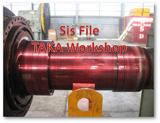
Transportation to Workshop

.
Preparation for mechanical inspectio
ROUND OUT INSPECTION
Electrical Round Out
Electrical Round out data


Max deviation round out exciter end
= 0.721Volts
= 721 mVolts
= 3.605 mils
= 0.0915 mm
Max deviation round out turbine end
= 0.301 Volts
= 301 mVolts
= 1.505 mils
= 0.0382 mm
= 721 mVolts
= 3.605 mils
= 0.0915 mm
Max deviation round out turbine end
= 0.301 Volts
= 301 mVolts
= 1.505 mils
= 0.0382 mm
NDT INSPECTIONS


-
4. SUMMAY
Rotor to be inspected when rotor was successfully removed from the stator bore,
1. Rotor Forging, retaining rings, found totally damaged on the rotor forging including body flex slot, slot dovetail, both retaining rings, retaining rings locking ,steel wedge at end portions close to retaining rings, see previous pages
NDT and round-out also has been inspected, found minor scratching due to electrical discharge and minor deflection on the journal at exciter end side but still in tolerance.
2. Rotor winding, Rotor winding is not possible to be measured by electrical measurements, due to the winding was totally damaged.
3. Rotor Shaft dimensional ,
Rotor shaft has been inspected using mechanical run-out and ERO, rotor shaft dimensional have a minor deflection
Exciter side journal shaft.
Diameter = 355.55 – 355.57 mm, max TIR = 0.05 mm
Turbine end journal shaft
Diameter = 355.56 – 355.58 mm. max TIR = 0.02 mm
5. CONCLUSION
1. Rotor forging, total damaged
2. Both retaining rings, heavy crack
3. Steel wedges, some of them was melted and almost of them was overheated
4. Copper bars winding rotor, melting
5. Journal shaft, minor scratch
6. Shaft, minor deflection
Total damaged on the rotor forging and retaining rings, repair is not possible, new unit must be planned to replace it.
