Emails:
sis_cahya@yahoo.com
siscahyabhuwana@gmail.com
Mobile phone:
+62 81311422270
I. GENERATOR INFORMATION
Generator type ________________ : Round Rotor.
Cooling Systems ______________ : H2 Cooled.
Station / Company where installed __:JAKARTA. INDONESIA.
Prime mover type ______________:GasTurbine.
Manufacture __________________:General Electric.
Date of machine manufacture _____:1992.
Year machine installed __________:1993.
Date of last rewind for Stator ______: N/A.
Rotor ________________________: NA.
Date of last major inspection ______: N/A.
Operating hours since last O/H ____:15 years.
Present services performed ___: by Siswanto ( PT.KARTIKA SIGMA INDONESIA and PT.TAKA Turbomachinery Indonesia).
Services Performed Inspection of stator : with ELCID and NDT on the rotor shaft.
GENERATOR TECHNICAL SPECIFICATION
Name plate data
Maker ______________________: General Electric
Type _______________________: H2 Cooled
Serial Number ________________: 335X944
Year ________________________: 1992,
Output _______________________: 142 000 KVA
Pf __________________________: 0.8
Speed ______________________: 3000RPM
Freq________________________ : 50 Hz
Armature Voltage_______________: 11,500 Volts
Armature Ampere_______________: 7,129 Amps
Field Ampere__________________: 1,274 Amps
Exciter Volts___________________: 500 Volts
Max KVA one cooler out of service ___113,600
No Load Field Current ___________: 440 Amperes
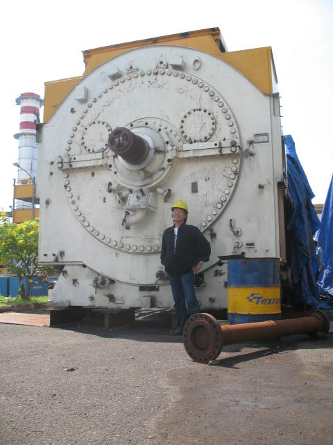
A. BACKGROUND
The station unit is a Combine Cycle Power Plant, consists of : 3 x125 MW GE Gas Turbine Generators and 1 x 185 MW GE Steam Turbine Generator
Generator was breakdown due to high reverse power attack from GSU 150 kV Transformer, inspection has been carried out with limited access when rotor still in place by top cover TE side removal, following are inspections summary on November 8-9, 2010 :
Generator was breakdown due to high reverse power attack from GSU 150 kV Transformer, inspection has been carried out with limited access when rotor still in place by top cover TE side removal, following are inspections summary on November 8-9, 2010 :
o Insulation Resistance on Stator and rotor winding
o Winding DC Resistance on Stator and Rotor winding
o Surge comparison on Stator and rotor winding.
o Winding DC Resistance on Stator and Rotor winding
o Surge comparison on Stator and rotor winding.
B. VISUAL INSPECTION-
Stator end winding region , found brittle, too dry and discoloring due to overheating
- Stator end winding coil blocking and ties, found broken and loose
- Stator Winding resin was found melt
- Surge ring ties and blocking, found melt
- Resin melt also found on the retaining Rings support holes
- Carbonized and carbon dirt were deposit on the stator winding and retaining ring top and inside


Discoloring on end winding insulation due to overheating attack

Found Resin melt on endwinding region

Resin melt found on the retaining rings surface

C. MEASUREMENTS
1. Winding DC Resistancea. Winding Resistance on Rotor Winding
JK resistance at 32 0C = 0.00586 ohm
Factory measurement at 25 0C = 0.252 ohm
After correcting to base factory temperature measurement to 25 0C
The deviation is round 190%.

Factory measurement at 25 0C = 0.252 ohm
After correcting to base factory temperature measurement to 25 0C
The deviation is round 190%.


b. Winding DC Resistance on Stator winding
Winding were measure at each phase with neutral connection was remove / open.
Measurement temperature : 270C
Phase U : 1.4 milliohm
Phase V : 1.4 milliohm
Phase W : 1.4 milliohm
Factory measurement for each phase at 100 C= 1.78 milliohm
Based on this measurement no significant deviation were found, is indicate no turn insulation short.
2. Insulation Resistance
a. Insulation Resistance on rotor Winding
Insulation Resistance to be measured by 500 VDC Mega ohm meter and digital multi meter.
Measurement was carried out from JK lead cables to ground / rotor body.
Measurement by 500 VDC Megger® = 0.0 MOhm
Measurement by digital milliohm meter = 2.6 milliohm
PI (polarization index), can’t to be measured due to winding was solid grounded
Measurement was carried out from JK lead cables to ground / rotor body.
Measurement by 500 VDC Megger® = 0.0 MOhm
Measurement by digital milliohm meter = 2.6 milliohm
PI (polarization index), can’t to be measured due to winding was solid grounded


b. Insulation Resistance on stator winding
Insulation Resistance was measured at phase to phase and phases to ground with Neutral connection were removed or open.
Phase R – S : 5.06 GΩ Voltages 5000 VDC
Phase R – T : 1.90 GΩ Voltages 5000 VDC
Phase S – T : .953 GΩ Voltage 5000 VDC
Phase R – G : 2.24 GΩ Voltage 5000 VDC
Phase S – G : 1.98 GΩ Voltage 5000 VDC
Phase T – G : 0.6 MΩ Voltage was drop to 890 VDC

Phase R – S : 5.06 GΩ Voltages 5000 VDC
Phase R – T : 1.90 GΩ Voltages 5000 VDC
Phase S – T : .953 GΩ Voltage 5000 VDC
Phase R – G : 2.24 GΩ Voltage 5000 VDC
Phase S – G : 1.98 GΩ Voltage 5000 VDC
Phase T – G : 0.6 MΩ Voltage was drop to 890 VDC

3. SurgeComparison
a. Rotor surge measurement
Surge was measured on JK lead outgoing to surge and to ground, with lead connection to instruments, lead 1-2 in active and ground. Applied on 500 Volts a.c.
Very small amplitude was found during surge measurement and surge voltage was drop from 500 Volts to 20 Volts.
Voltage drop is resulting by the degradation of winding impedance due to short to ground.
See illustration bellows:
b. Stator surge measurement
Very small amplitude was found during surge measurement and surge voltage was drop from 500 Volts to 20 Volts.
Voltage drop is resulting by the degradation of winding impedance due to short to ground.
See illustration bellows:
b. Stator surge measurement
Surge were measure at each phase at app. 5000 volts a.c,
Phase “R” and “S” are typical result.When surge voltage was applied 5000 V.a.c on these winding, no significant voltage drop and no short indication were found.
Voltage measurement 5000 V a.c were drop to 5030 volts
Phase “ T ” :Voltage surge, the winding were not found solid breakdown to ground (voltage applied from surge instrument is 5000 V (lead “ 3 “ active) but its significantly drop when measurement being done is drop to 730 V., the winding has not solid breakdown but it’s found very low resistance due to degradation of wall insulation..


Rotor measurement

Stator measurement
D. SUMMARY
Based on these inspections we can summarized to the following parameters and conditions
1. Rotor winding : as physical and measurement were found overheating and solid grounded
Based on these inspections we can summarized to the following parameters and conditions
1. Rotor winding : as physical and measurement were found overheating and solid grounded
2. Stator winding
a. as measurement inspections:
• no solid grounded were found on the phases R / S /T as well between phases.
• Very low insulation resistance was found on the phase “T”, its can resulting by carbon dusting in the winding and or degradation of wall insulations.
• Winding resistance still in balance and in tolerance based on the factory measurements, no inter turn short were found
b. Physical inspections
• Found brittle , discoloration and overheating on whole of insulation systems
• Found melting on the resin stator insulation winding
• Found melting on the surge winding support ties and blocking
3. Summary for Stator
Whole of stator insulation come degradations and overheating
